The ZX Spectrum started me down the path as a maker in the 80’s, it was my first computer, and I had so much fun and learning with it. I always wanted to build a spectrum clone when I was young, but I don’t have the skills and resources.
Originally I wanted to make a retropie emulator but was quite turned off with the long loading time and navigation. So my idea was to have it much closer to the original experience with the machine when I was young.
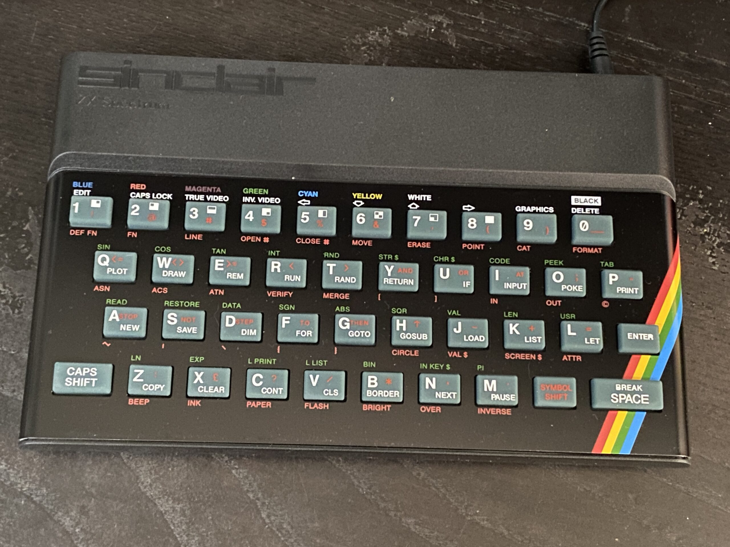
While researching for a better Spectrum emulator, I stumbled on a RasPi bare metal emulator, the “ZXBaremulator” it boots at without going into the Linux screens. I have an old RasPi 1 Model B to hack with, and without thinking much, I ordered a recreated casing, keyboard membrane and faceplate from ZX Renew and waited patiently for it. I was disappointed when It came two weeks later in the mail; I did not order the rubber mat (I thought it was a mouse pad or something). So I placed another order for the mat (paid another £15 for shipping)
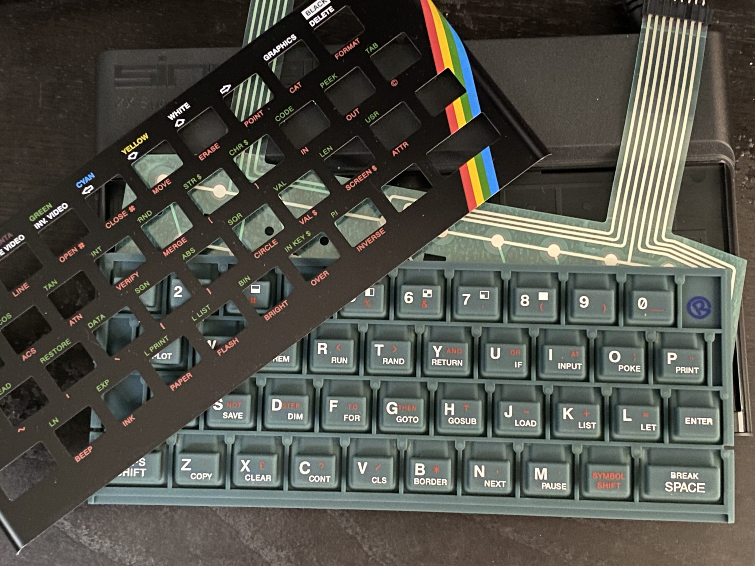
Another two weeks passed, and I finally got the recreated case and started hacking the RasPi to fit the case.
Everything works fine except for one crucial part that doesn’t work for me; I cannot load tape the slow and regular way; that takes away the ’80s experience.
So I started looking for other solutions, and I decided to design and build a clone from scratch.
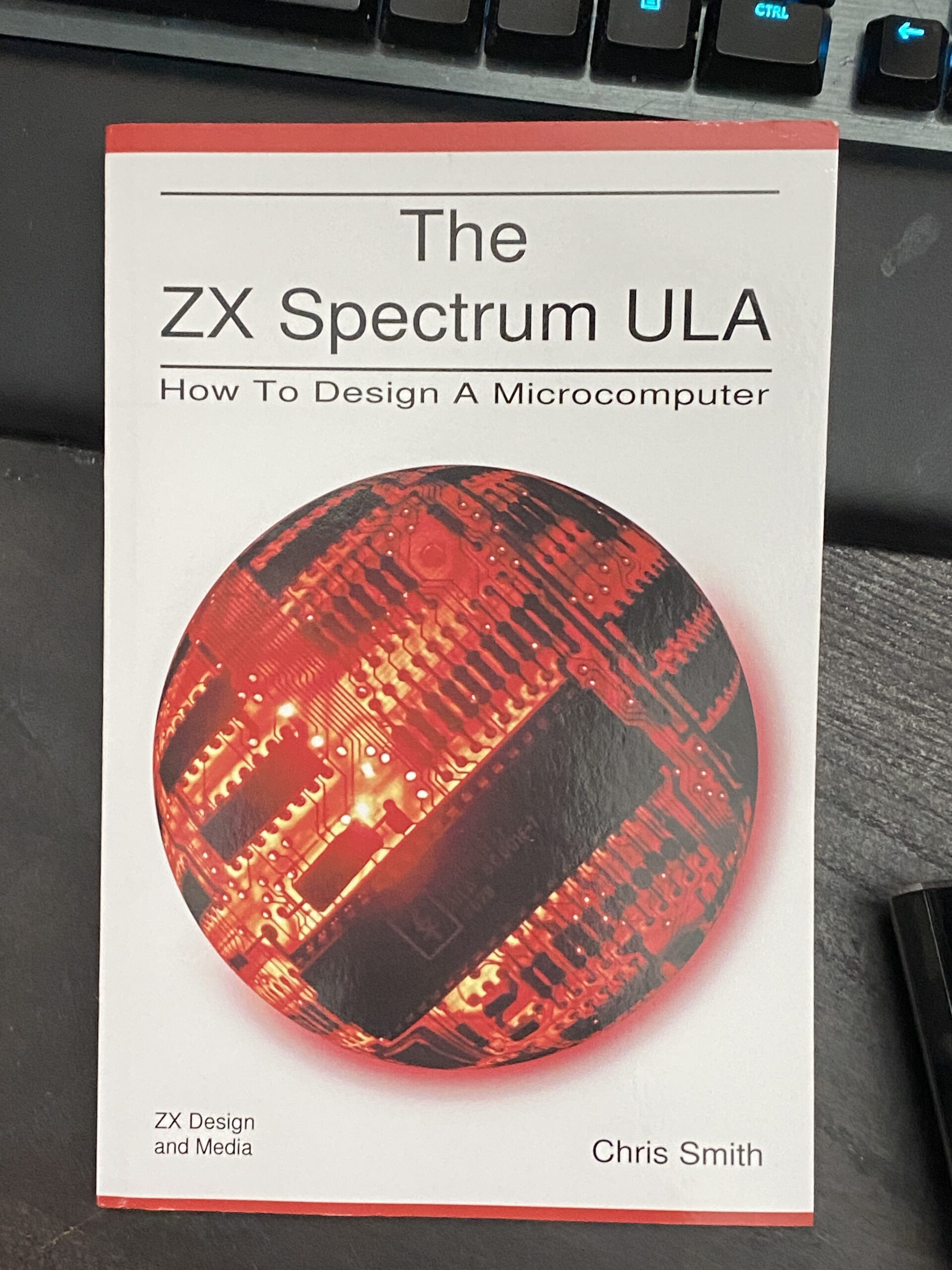
As part of my research, I ordered the book that everyone recommends for building a spectrum clone, “The ZX Spectrum ULA” by Chris Smith; it is a very well-written and informative book. I spent many nights reading and pondering my approach to building a Spectrum clone.
While researching, I found several open-source ZX Spectrum projects, like the Harlequin 48K / 128K, ZX Uno, and many more. And of course, I lust over the Spectrum Next, hoping to support the 3rd issue in the future if there is one.
In the end, I decided not the reinvent the wheel and pick a project to work on; I chose the “sizif 512K” as it is the closest to what I wanted and more. I wanted a clone that uses as many real parts as possible, especially a real Z80. The only problem I have is there is little guidance in building this clone; I will have to spend some time figuring everything out and sourcing for parts.
Hi
I’m about to embark on building my own Sizir-512 too,
while I have built several projects before of this complexity I have found that the BOM has a few components that are a little difficult to decipher.
Do you have a list of any alternatives or sources from when you ordered your parts that you could possibly share please?
Regards
Craig
Most of the parts are ordered from China, the Z80, AY, EEPROM, SRAM are sourced from the 2nd Hand market in China.
Other parts are from various sellers in China. Keyboard connectors from Digi-Key.
Let me know which parts you need help with, see if I can help you with it.
I do have a complete set of components and PCB. Main parts are new from Digi-Key or Element-14. Let me know if you are interested.
I also have spare M18 Bluetooth module, cables, switches etc.
let me know why you need, can let you have it at cost + shipping.
Thanks for your reply,
I spent quite a few hours yesterday looking for the complete BOM and I think I have everything I need (fingers crossed for the validity of the second hand chips)
However I’m confused about one of the inductors and the memory card slot it seems for the inductor you have a choice (L1,L2) and are both memory card slots required or can we use one or the other…
I’ts just a case of waiting for the parts now
I thank you for your offer of help, I’m sure I may need it at some point considering how little there is on the regarding building this project.
Regards
Craig
Some parts are duplicated, or for you to choose between parts. You only need 1 memory card type, whichever is available.
I think the only 2nd chip is the AY sound chip. Safer if you get it from one the Facebook groups.
https://www.facebook.com/groups/SinclarForSale/?ref=share
Out of curiosity, once built, is the machine able to update is ROM directly or does the operation still need the EPROM flasher ?
There is a write enable but I am not sure how to do it.
Build almost complete (just waiting for the AD724) unfortunately I think I have fake EMP1270 as I’m unable to program the CPLD as it fails “Unable to scan device chain” 🙁
After reading your blog I made sure the whole power circuit was in place before I attempted to program the chip.
Looking at the two chips I received one of them does not have the pin 1 dimple (this is the one I have fitted) so I’m quite sure it’s been sanded and rebadged 🙁
Do you have a reliable source for this chip at all or any recommendations for tests I can run to double check my build?
Regards
Craig
The only reliable source I have is from Chinese sellers. I ordered twice, and they seem legit.
Link to my purchase.
https://item.taobao.com/item.htm?spm=a1z09.2.0.0.7e192e8duxSce3&id=611069754382&_u=r2jmmfj23429
Let me know if I can assist you in any way.
Well after desoldering the suspect cpld and then hand soldering a replacement I ran into the same issue … time to get the Multimeter out.
Readings appeared to be off so after going over my soldering and tracing back I could find no issues, that’s when I decided to check the PSU … I had mistakenly been using a 5v PSU instead of my 12v !!!
After rectifying this stupid error programming the CPLD completed without any issues.
Annoyingly now I cannot find my megadrive cable to test but I’m hopeful everything else is working fine.
I’ll update you once I have tested.
Regards
Craig
Nice, Glad you got it working. After this it is quite easy.
I will post some update on some mods, internal speakers , Bluetooth tape input. Join my group and post your experience of you can. https://www.facebook.com/groups/880860392863057/?ref=share